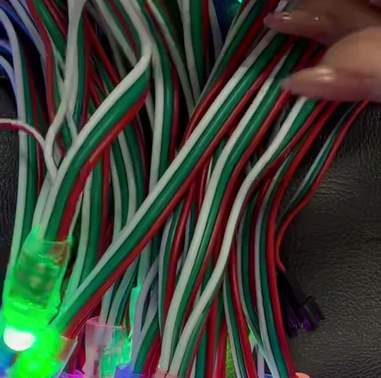
Wire the string to a T‑1000S
| Terminal or supply | Pixel string wire |
|---|---|
| T‑1000S · DAT on the signal-output side | Green · DIN at the 3-pin female connector on the input end |
| T‑1000S · GND on the signal-output side | White · Common ground with power supply negative |
| +5 V DC supply positive | Loose red power lead |
| Power supply negative (V−) | Loose white power lead |
| T‑1000S · CLK | Leave unconnected |
Find the terminals by their DAT and GND labels. Some diagrams show the white ground wire in black so it is easier to see. The loose red and white leads power the string. Power the controller through its own input according to the markings on your unit. T‑1000S
Troubleshoot by symptom
The T‑1000S ERROR light flashes
Power off the controller before removing the SD card. Check that the card is compatible, uses the format specified in your unit’s manual, and contains a .led file generated for the correct controller model and LED chip.
The entire string is dark
Check voltage, polarity, common ground, and the DAT → DIN connection. With power disconnected, connect a short known-good section and test at low brightness. On a T‑1000S, choose a WS2811-compatible profile in LedEdit and check that the SD card program loads.
Pixels go dark from one point onward
Confirm the program covers all connected pixels. Find the last pixel that lights and the first that fails. Disconnect power and inspect the splice between them. The fault may be at the previous DOUT, the next DIN, or the power connection at the next pixel.
The far end dims or flickers at high brightness
If lowering brightness helps, check power and connectors. At the same brightness, measure DC voltage between V+ and GND at the input and far end. If voltage drops at the far end, check the wire gauge and consider feeding 5 V to that section. Keep a common ground and avoid joining the positive outputs of independent supplies.
Colors are swapped or one pixel loses a color
Test red, green, and blue separately. If colors swap the same way across the whole string, check the controller’s color order. If only one pixel consistently loses a color and later pixels work, inspect or replace that pixel.
Repair the string
Gather a multimeter, wire strippers, correctly sized insulated connectors or soldering tools, heat-shrink tubing, and a matching 5 V WS2811 pixel if needed.
Identify the wires
Disconnect the supply and controller. Photograph the splice and label V+, GND, DIN, and DOUT. Check continuity only with power disconnected and the lead or splice isolated. A continuity check between DIN and DOUT cannot test the driver chip.
Fix the wire or replace the pixel
Remove the damaged wire. If replacing a pixel, leave enough wire on both sides. On this model, join red to red and white to white. Connect the previous DOUT to the replacement’s DIN, then its DOUT to the next DIN. To bypass a pixel, join the previous DOUT directly to the next DIN and maintain V+ and GND. Adjust the program if you permanently remove a pixel.
Insulate and check the splices
Use insulated connectors or solder and cover each splice separately with heat-shrink tubing. Reseal outdoor splices and add strain relief. Before applying power, check for exposed copper and shorts between +5 V, GND, and data.
Test at low brightness
Test red, green, and blue, then run a pattern that lights pixels in sequence. Verify that both sides of the splice respond and that the joint stays cool.
Video demonstration
This silent demo shows wire preparation and a power-on test. Insulate all three splices before applying power.